US1683096A - Rotary jar - Google Patents
Rotary jar Download PDFInfo
- Publication number
- US1683096A US1683096A US466050A US46605021A US1683096A US 1683096 A US1683096 A US 1683096A US 466050 A US466050 A US 466050A US 46605021 A US46605021 A US 46605021A US 1683096 A US1683096 A US 1683096A
- Authority
- US
- United States
- Prior art keywords
- section
- jar
- rotary
- nut
- plunger
- Prior art date
- Legal status (The legal status is an assumption and is not a legal conclusion. Google has not performed a legal analysis and makes no representation as to the accuracy of the status listed.)
- Expired - Lifetime
Links
Images
Classifications
-
- E—FIXED CONSTRUCTIONS
- E21—EARTH DRILLING; MINING
- E21B—EARTH DRILLING, e.g. DEEP DRILLING; OBTAINING OIL, GAS, WATER, SOLUBLE OR MELTABLE MATERIALS OR A SLURRY OF MINERALS FROM WELLS
- E21B31/00—Fishing for or freeing objects in boreholes or wells
- E21B31/107—Fishing for or freeing objects in boreholes or wells using impact means for releasing stuck parts, e.g. jars
Definitions
- My invention relates to a rotary jar to be employed in connection with the rotary method of drilling oil and artesian wells.
- the general object of my invention is to pro- 6 vide an improved apparatus and an improved method for facilitating the loosening up of a drill pipe or casing which has become frozen.
- a further object of my invention is to provide a rotary jar of the character referred to with improved and durable impact surfaces.
- a further object of my invention is to provide such a rotary jar with driving connections which will maintain rotatable connection within the device at all times.
- a further object of my invention is to provide a simplified device of the character referred to which will be economical in manufacture 'and extremely durable in use.
- a further object of my invention is to provide in such a device drive and driven members which may be each formed integral and yet readily assembled.
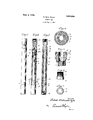
- Figure 1 is a vertical elevation of a rotary jar embodying my invention, illustrating the drive and driven members in completely telescoped position.
- Fig. 2 is a vertical elevation 'tion of the device of Fig. 1.
- Fig. 3 is a complete vertical section of the device of Figs. 1 and 2.
- Fig. 4 is a horizontal section taken on a line indicated by w m in Fig. 2.
- Fig. 5 is a detail view partly in section of the" hammerhead of the driven member.
- Fig. 6 is a detail view of the split nut or hammer head carried on the drive member.
- Fig. 7 is a plan view of the nut or hammer head illustrated in Fig. 6.
- I construct the jar with a tubular section and a plunger section movable longitudinally within the same during the jarring movement, and I provide means on the plunger member and on the tubular section cooperating to permit the transmission of rotary movement from one section to the other; in addition to this I provide a water circulating opening through the plunger. and provide packing means to prevent escape of water passing through the jar.
- the jar includes a tubular section or barrel 2 connected at its upper end to the pipe string; this barrel 2 is the driving section of the jar; movable longitudinally within this barrel, I provide a plunger section 3.
- the drive member 2 comprises a hollow tubular or pipe-like section having a central chamber 4 open at its lower end and communlcating with a smaller bore 5 extending through the upper end.
- the upper end of the drive member 2 is provided with a tapered box 6 for connection with a rotary drill pipe.
- any suitable means may be provided to enable rotary movement to e imparted from the driving member to the driven member.
- I provide a part or driving means on the dr ving member to engage a part on the driven member to impart this rotary movement.
- the lower end of the drive member 2 is threaded to receive an impact nut or hammer head 7.
- This impact nut or hammer head 7 is provided with a hexagonal bore 8 and a reduced threaded portion to be screwthreaded within the lower end of the drive member 2.
- the nut or hammer head 7 is provided with a down impact surface 9 and up impact surface 10.
- the nut or hammer head 7 is split but when screw-threaded on to the drive member 2 functions as an integral structure.
- the driven member 3 has an elongated hexagonal body or stem adapted to slidably engage with the hexagonal bore 8 of the nut or hammer head 7, and is provided with a bore 11 extending throughout its length and preferably registering with the bore 5 of the drive member 2.
- the driven member 3 has an integral head 3 formed at its opposite ends with opposed anvil members providing jar up impact surface 12 and jar down impact surface 13.
- the lower end of'the driven member 3 is provided with a tapered box 14 for connection with the rotary drill pipe.
- the device In operating in accordance with'my method the device is inserted within and becomes a portion of a rotary drill pipe by connecting the drive member 2 at the top to one section of the rotary drill pipe and the driven member 3 at the bottom to another section of the rotary drill pipe; that is to say, it constitutes an extensible driving connection between the upper and lower sections of the drill string.
- the device provides a hammer head (comprising the nut 7) positioned between opposed anvil members (the jar down anvil member having impact shoulder or surface 13 and the jar up anvil member having impact surface 12).
- a hammer head comprising the nut 7
- opposed anvil members the jar down anvil member having impact shoulder or surface 13 and the jar up anvil member having impact surface 12.
- I preferably provide the upper end of the driven member 3 with a reduced threaded portion 15 defining an annular shoulder 16.
- I place a washer or packing member 17 and secure the same by means of a threaded collar or ring 18.
- the device enables the drill pipe or string to be released by jarring.
- the device provides a hammer head interposed between opposed anvil members.
- the drill pipe may be jarred down by elevating its uppersection, that is, the portion of the string above the device, until the drive member 2 has been lifted relative to the driven member 3 and the twomembers thereby relatively telescopically extended.
- the upper section of the string may then be released or run down with great rapidity and a violent jar down procured by the down impact surface 9 of the hammer head 7 striking the impact surface 13 of the lower anvil member. After jarring in this way, I rotate the lower section through the jar connection.
- That portion of the string above the device is relatively lowered until the driven member 3 is completely telescoped within the drive member 2 as illustrated in Fig. 2.
- the upper portion of the string above the device may thereupon be rapidly raised and a violent ar up will be produced by the striking of the up impact surface 10 of the hammer head upon the impact surface 12 of the upper anvil member.
- the jar up or jar down may be successively repeated until the wedging or jamming of the drill pipe or string has been relieved. If desired the device enables an alternate jar up and jar down of great rapidity and violence by merely sufiiciently reciprocating that portion of the drive stem above the device.
- the rotary drive connection between the members 2 and 3 is maintained by the inter-engaging hexagonal formation of the stem of the driven member 3 and the nut or hammer head 7.
- a hexagonal formation is merely a preferable formation, it being obvious that a square, octagonal or ribbed arrangement would be possible.
- the drive connection is in no manner dependent upon the impact surfaces, and I prefer a hexagonal arrangement for manufacturing and engineering reasons. With this arrangement of independent drive connections and impact surfaces the battering of the impact surfaces will not interfere with the drive connection which must necessaril be maintained in the drill string in normal operation. Furthermore, the arrangement of simple impact surfaces and simple drive conncctions which are possible because the same are independent, reduces materially the cost of manufacture of the device in addition to greatly enhancing its durability.
- the split nut 7 I have made possible the formation of the upper and lower anvil members integral with the driven member 3. It is an advantage in manufacture and in the durability of the device to make these anvil members integral with the device and by splittin the nut 7 assembly is made possible for such integral structure. For example, to assemble the part-s are positioned so that the upper anvil member will be telescoped within the drive member 2 to a point above the place for the nut 7 before said nut is 'positioned. Thereupon the two portions of the nut 7 are placed around the stem of the driven member 3 and the drive member and member 2 relatively rotated to screw-thread the nut 7 in position.
- my invention provides an extremely simple and practical method for loosening adrill string and provides for effecting this result by means Which is economical in manufacture and extremely durable in operation.
- My invention is not limited to the particular inter-relation or formation of parts described for a preferred embodiment thereof but is of the scope and extent set forth in the following claims.
- a tubular outer section and a tubular plungersection within the outer section said plunger section having a head on its inner end, an impact-nut having a thread connection securing the same in the end of the outer section, constructed to receive all the impact of said head upon its inner end when the jar is jarred in one direction, said plunger section having an annular shoulder at its end remote from said head to strike the other end of said impact nut and take all the impact when the jar is jarred in the other direction
- said outer tubular section having a bore at one end cooperating with the tubular plunger-section to pass section having means cooperating to enable 2 circulating water through the jar.
- a tubular section and a plunger-section movable longitudinally within the tubular section during the jarring movement, said plunger section having an angular part and said tubular section having means to cooperate with the angular part to enable a rotary movement to be imparted from one section to the other, said plunger section having a water-circulating passage extending longitudinally therethrough, and means for packing the jar to prevent the escape of the water in passing through the same.
Description
Patented Sept. 4, 1928.
UNITED STATES ROBERT MCDONALD PYLES, OF FULLERTON, CALIFORNIA.
ROTARY JAR.
Application filed May 2, 1921. Serial No. 466,050.
My invention relates to a rotary jar to be employed in connection with the rotary method of drilling oil and artesian wells. The general object of my invention is to pro- 6 vide an improved apparatus and an improved method for facilitating the loosening up of a drill pipe or casing which has become frozen.
A further object of my invention is to provide a rotary jar of the character referred to with improved and durable impact surfaces.
A further object of my invention is to provide such a rotary jar with driving connections which will maintain rotatable connection within the device at all times.
A further object of my invention is to provide a simplified device of the character referred to which will be economical in manufacture 'and extremely durable in use.
A further object of my invention is to provide in such a device drive and driven members which may be each formed integral and yet readily assembled.
Other objects and advantages in the following description of form of my invention.
In the drawings:
Figure 1 is a vertical elevation of a rotary jar embodying my invention, illustrating the drive and driven members in completely telescoped position.
Fig. 2 is a vertical elevation 'tion of the device of Fig. 1. V
Fig. 3 is a complete vertical section of the device of Figs. 1 and 2.
Fig. 4 is a horizontal section taken on a line indicated by w m in Fig. 2.
Fig. 5 is a detail view partly in section of the" hammerhead of the driven member.
Fig. 6 is a detail view of the split nut or hammer head carried on the drive member.
Fig. 7 is a plan view of the nut or hammer head illustrated in Fig. 6.
In practicing my invention, I construct the jar with a tubular section and a plunger section movable longitudinally within the same during the jarring movement, and I provide means on the plunger member and on the tubular section cooperating to permit the transmission of rotary movement from one section to the other; in addition to this I provide a water circulating opening through the plunger. and provide packing means to prevent escape of water passing through the jar. I shall now describe the preferred apparatus for this purpose.
will appear a preferred partly in sec- The jar includes a tubular section or barrel 2 connected at its upper end to the pipe string; this barrel 2 is the driving section of the jar; movable longitudinally within this barrel, I provide a plunger section 3.
The drive member 2 comprises a hollow tubular or pipe-like section having a central chamber 4 open at its lower end and communlcating with a smaller bore 5 extending through the upper end. The upper end of the drive member 2 is provided with a tapered box 6 for connection with a rotary drill pipe.
Any suitable means ma be provided to enable rotary movement to e imparted from the driving member to the driven member. I provide a part or driving means on the dr ving member to engage a part on the driven member to impart this rotary movement. In order to accomplish this and at the same time provide for producing a jar movement, the lower end of the drive member 2 is threaded to receive an impact nut or hammer head 7. This impact nut or hammer head 7 is provided with a hexagonal bore 8 and a reduced threaded portion to be screwthreaded within the lower end of the drive member 2. Thereby the nut or hammer head 7 is provided with a down impact surface 9 and up impact surface 10. For a purpose hereinafter set forth the nut or hammer head 7 is split but when screw-threaded on to the drive member 2 functions as an integral structure.
The driven member 3 has an elongated hexagonal body or stem adapted to slidably engage with the hexagonal bore 8 of the nut or hammer head 7, and is provided with a bore 11 extending throughout its length and preferably registering with the bore 5 of the drive member 2. The driven member 3 has an integral head 3 formed at its opposite ends with opposed anvil members providing jar up impact surface 12 and jar down impact surface 13. The lower end of'the driven member 3 is provided with a tapered box 14 for connection with the rotary drill pipe.
In operating in accordance with'my method the device is inserted within and becomes a portion of a rotary drill pipe by connecting the drive member 2 at the top to one section of the rotary drill pipe and the driven member 3 at the bottom to another section of the rotary drill pipe; that is to say, it constitutes an extensible driving connection between the upper and lower sections of the drill string.
Thus positioned within the rotary drill pipe the device provides a hammer head (comprising the nut 7) positioned between opposed anvil members (the jar down anvil member having impact shoulder or surface 13 and the jar up anvil member having impact surface 12). During the normal drilling operation, rotatable connection will be maintained in the drill pipe and Within the device by the inter-engaging of the hexagonal stem of the driven member 3 with the hexagonal bore 8 of the nut or hammer head 7. The device will, therefore, not interfere with the normal rotatory action of the drill pipe. Furthermore, the circulation course throughout the rotary drill pipe will be maintained through the device by means of the bores 11 and 5, thereby not interfering with the rotary drilling operation. I provide any suitable packing means. For this purpose at the union between the members 2 and 3, I preferably provide the upper end of the driven member 3 with a reduced threaded portion 15 defining an annular shoulder 16. Upon the annular shoulder 16 I place a washer or packing member 17 and secure the same by means of a threaded collar or ring 18.
In case the drill pipe or string equipped with this device should become wedged or jammed the device enables the drill pipe or string to be released by jarring. In that behalf the device provides a hammer head interposed between opposed anvil members. For example, the drill pipe may be jarred down by elevating its uppersection, that is, the portion of the string above the device, until the drive member 2 has been lifted relative to the driven member 3 and the twomembers thereby relatively telescopically extended. The upper section of the string may then be released or run down with great rapidity and a violent jar down procured by the down impact surface 9 of the hammer head 7 striking the impact surface 13 of the lower anvil member. After jarring in this way, I rotate the lower section through the jar connection.
To jar up, that portion of the string above the device is relatively lowered until the driven member 3 is completely telescoped within the drive member 2 as illustrated in Fig. 2. The upper portion of the string above the device may thereupon be rapidly raised and a violent ar up will be produced by the striking of the up impact surface 10 of the hammer head upon the impact surface 12 of the upper anvil member.
In practice the jar up or jar down, as the case may be, may be successively repeated until the wedging or jamming of the drill pipe or string has been relieved. If desired the device enables an alternate jar up and jar down of great rapidity and violence by merely sufiiciently reciprocating that portion of the drive stem above the device.
It should be noted that the rotary drive connection between the members 2 and 3 is maintained by the inter-engaging hexagonal formation of the stem of the driven member 3 and the nut or hammer head 7. Of course, a hexagonal formation is merely a preferable formation, it being obvious that a square, octagonal or ribbed arrangement would be possible. One of the advantages of the arrangement is that the drive connection is in no manner dependent upon the impact surfaces, and I prefer a hexagonal arrangement for manufacturing and engineering reasons. With this arrangement of independent drive connections and impact surfaces the battering of the impact surfaces will not interfere with the drive connection which must necessaril be maintained in the drill string in normal operation. Furthermore, the arrangement of simple impact surfaces and simple drive conncctions which are possible because the same are independent, reduces materially the cost of manufacture of the device in addition to greatly enhancing its durability.
By the provision of the split nut 7 I have made possible the formation of the upper and lower anvil members integral with the driven member 3. It is an advantage in manufacture and in the durability of the device to make these anvil members integral with the device and by splittin the nut 7 assembly is made possible for such integral structure. For example, to assemble the part-s are positioned so that the upper anvil member will be telescoped within the drive member 2 to a point above the place for the nut 7 before said nut is 'positioned. Thereupon the two portions of the nut 7 are placed around the stem of the driven member 3 and the drive member and member 2 relatively rotated to screw-thread the nut 7 in position.
I consider that my invention provides an extremely simple and practical method for loosening adrill string and provides for effecting this result by means Which is economical in manufacture and extremely durable in operation. My invention is not limited to the particular inter-relation or formation of parts described for a preferred embodiment thereof but is of the scope and extent set forth in the following claims.
I claim:
1. In a rotary jar, the combination of a tubular outer section and a tubular plungersection within the outer section, said plunger section having a head on its inner end, an impact-nut having a thread connection securing the same in the end of the outer section, constructed to receive all the impact of said head upon its inner end when the jar is jarred in one direction, said plunger section having an annular shoulder at its end remote from said head to strike the other end of said impact nut and take all the impact when the jar is jarred in the other direction, said outer tubular section having a bore at one end cooperating with the tubular plunger-section to pass section having means cooperating to enable 2 circulating water through the jar.
2. In a rotary jar, the combination of a tubular section and a plunger-section within the tubular section, said plunger section having an integral head on its inner end, an impact-nut composed of sections disposed on opposite sides of the. plunger section, and secured in the end of the tubular section, said plunger section having an annular shoulder at its end remote from said head, to strike and cooperate with the impact nut, said impact nut having an angular opening and said plunger having an angular body fitting said opening to enable a rotary movement to be imparted from one of the sections to the other.
3. In a rotary jar, the combination of a tubular section and a plunger-section within the tubular section, said plunger section having an integral head on its inner end, said tubular section constructed to permit longi tudinal movement of said head within the tubular section, said plunger and said tubular a rotary movement to be imparted from one of the sections to the other, said plunger section having a water-circulating passage extending longitudinally therethrough, and
means for packing the jar to prevent the escape of the water in passing through the same.
4. In a rotary jar, the combination of a tubular section and a plunger-section movable longitudinally within the tubular section during the jarring movement, said plunger section having an angular part and said tubular section having means to cooperate with the angular part to enable a rotary movement to be imparted from one section to the other, said plunger section having a water-circulating passage extending longitudinally therethrough, and means for packing the jar to prevent the escape of the water in passing through the same.
Signed at Los Angeles, California, this 16th day of April, 1921.
ROBERT MCDONALD PYLES.
Priority Applications (1)
| Application Number | Priority Date | Filing Date | Title |
|---|---|---|---|
| US466050A US1683096A (en) | 1921-05-02 | 1921-05-02 | Rotary jar |
Applications Claiming Priority (1)
| Application Number | Priority Date | Filing Date | Title |
|---|---|---|---|
| US466050A US1683096A (en) | 1921-05-02 | 1921-05-02 | Rotary jar |
Publications (1)
| Publication Number | Publication Date |
|---|---|
| US1683096A true US1683096A (en) | 1928-09-04 |
Family
ID=23850245
Family Applications (1)
| Application Number | Title | Priority Date | Filing Date |
|---|---|---|---|
| US466050A Expired - Lifetime US1683096A (en) | 1921-05-02 | 1921-05-02 | Rotary jar |
Country Status (1)
| Country | Link |
|---|---|
| US (1) | US1683096A (en) |
-
1921
- 1921-05-02 US US466050A patent/US1683096A/en not_active Expired - Lifetime
Similar Documents
| Publication | Publication Date | Title |
|---|---|---|
| US3208541A (en) | Spring biased well jar | |
| US5170843A (en) | Hydro-recocking down jar mechanism | |
| US2153883A (en) | Oil well jar | |
| US1785559A (en) | Stress and strain compensating joint for rotary well-drilling columns | |
| US2507585A (en) | Percussion tool for wells | |
| US3658140A (en) | Mechanical jar | |
| US2309866A (en) | Safety joint bumper sub | |
| US2146454A (en) | Vibrating well jar | |
| US2708100A (en) | Safety joint for oil well drilling stems | |
| US2671640A (en) | Well jarring apparatus | |
| US3316986A (en) | Rotary jar-type well tool | |
| US2474459A (en) | Jar | |
| US1683096A (en) | Rotary jar | |
| US1885043A (en) | Rotary jar | |
| US2214970A (en) | Combination well driving and boring tool | |
| US1344774A (en) | Tool-joint | |
| US4113038A (en) | Drilling jar | |
| US2837315A (en) | Hydrostatic bumper jar | |
| US2153882A (en) | Rotary jar | |
| US3307636A (en) | Jarring tool | |
| US1775673A (en) | Well-drill jar | |
| US2550142A (en) | Rotary jar | |
| US1907012A (en) | Drill pipe protector | |
| US1778252A (en) | Rotary jar | |
| US1821212A (en) | Impact bit |