EP0633303A1 - Combined-cycle power generation system using a coal-fired gasifier - Google Patents
Combined-cycle power generation system using a coal-fired gasifier Download PDFInfo
- Publication number
- EP0633303A1 EP0633303A1 EP94304246A EP94304246A EP0633303A1 EP 0633303 A1 EP0633303 A1 EP 0633303A1 EP 94304246 A EP94304246 A EP 94304246A EP 94304246 A EP94304246 A EP 94304246A EP 0633303 A1 EP0633303 A1 EP 0633303A1
- Authority
- EP
- European Patent Office
- Prior art keywords
- particles
- gas
- steam
- heat
- mixture
- Prior art date
- Legal status (The legal status is an assumption and is not a legal conclusion. Google has not performed a legal analysis and makes no representation as to the accuracy of the status listed.)
- Withdrawn
Links
Images
Classifications
-
- F—MECHANICAL ENGINEERING; LIGHTING; HEATING; WEAPONS; BLASTING
- F01—MACHINES OR ENGINES IN GENERAL; ENGINE PLANTS IN GENERAL; STEAM ENGINES
- F01K—STEAM ENGINE PLANTS; STEAM ACCUMULATORS; ENGINE PLANTS NOT OTHERWISE PROVIDED FOR; ENGINES USING SPECIAL WORKING FLUIDS OR CYCLES
- F01K23/00—Plants characterised by more than one engine delivering power external to the plant, the engines being driven by different fluids
- F01K23/02—Plants characterised by more than one engine delivering power external to the plant, the engines being driven by different fluids the engine cycles being thermally coupled
- F01K23/06—Plants characterised by more than one engine delivering power external to the plant, the engines being driven by different fluids the engine cycles being thermally coupled combustion heat from one cycle heating the fluid in another cycle
- F01K23/067—Plants characterised by more than one engine delivering power external to the plant, the engines being driven by different fluids the engine cycles being thermally coupled combustion heat from one cycle heating the fluid in another cycle the combustion heat coming from a gasification or pyrolysis process, e.g. coal gasification
-
- C—CHEMISTRY; METALLURGY
- C10—PETROLEUM, GAS OR COKE INDUSTRIES; TECHNICAL GASES CONTAINING CARBON MONOXIDE; FUELS; LUBRICANTS; PEAT
- C10J—PRODUCTION OF PRODUCER GAS, WATER-GAS, SYNTHESIS GAS FROM SOLID CARBONACEOUS MATERIAL, OR MIXTURES CONTAINING THESE GASES; CARBURETTING AIR OR OTHER GASES
- C10J3/00—Production of combustible gases containing carbon monoxide from solid carbonaceous fuels
- C10J3/46—Gasification of granular or pulverulent flues in suspension
- C10J3/466—Entrained flow processes
-
- C—CHEMISTRY; METALLURGY
- C10—PETROLEUM, GAS OR COKE INDUSTRIES; TECHNICAL GASES CONTAINING CARBON MONOXIDE; FUELS; LUBRICANTS; PEAT
- C10J—PRODUCTION OF PRODUCER GAS, WATER-GAS, SYNTHESIS GAS FROM SOLID CARBONACEOUS MATERIAL, OR MIXTURES CONTAINING THESE GASES; CARBURETTING AIR OR OTHER GASES
- C10J3/00—Production of combustible gases containing carbon monoxide from solid carbonaceous fuels
- C10J3/46—Gasification of granular or pulverulent flues in suspension
- C10J3/54—Gasification of granular or pulverulent fuels by the Winkler technique, i.e. by fluidisation
-
- C—CHEMISTRY; METALLURGY
- C10—PETROLEUM, GAS OR COKE INDUSTRIES; TECHNICAL GASES CONTAINING CARBON MONOXIDE; FUELS; LUBRICANTS; PEAT
- C10J—PRODUCTION OF PRODUCER GAS, WATER-GAS, SYNTHESIS GAS FROM SOLID CARBONACEOUS MATERIAL, OR MIXTURES CONTAINING THESE GASES; CARBURETTING AIR OR OTHER GASES
- C10J3/00—Production of combustible gases containing carbon monoxide from solid carbonaceous fuels
- C10J3/72—Other features
- C10J3/82—Gas withdrawal means
- C10J3/84—Gas withdrawal means with means for removing dust or tar from the gas
-
- C—CHEMISTRY; METALLURGY
- C10—PETROLEUM, GAS OR COKE INDUSTRIES; TECHNICAL GASES CONTAINING CARBON MONOXIDE; FUELS; LUBRICANTS; PEAT
- C10K—PURIFYING OR MODIFYING THE CHEMICAL COMPOSITION OF COMBUSTIBLE GASES CONTAINING CARBON MONOXIDE
- C10K1/00—Purifying combustible gases containing carbon monoxide
- C10K1/002—Removal of contaminants
- C10K1/003—Removal of contaminants of acid contaminants, e.g. acid gas removal
- C10K1/004—Sulfur containing contaminants, e.g. hydrogen sulfide
-
- C—CHEMISTRY; METALLURGY
- C10—PETROLEUM, GAS OR COKE INDUSTRIES; TECHNICAL GASES CONTAINING CARBON MONOXIDE; FUELS; LUBRICANTS; PEAT
- C10K—PURIFYING OR MODIFYING THE CHEMICAL COMPOSITION OF COMBUSTIBLE GASES CONTAINING CARBON MONOXIDE
- C10K1/00—Purifying combustible gases containing carbon monoxide
- C10K1/04—Purifying combustible gases containing carbon monoxide by cooling to condense non-gaseous materials
-
- C—CHEMISTRY; METALLURGY
- C10—PETROLEUM, GAS OR COKE INDUSTRIES; TECHNICAL GASES CONTAINING CARBON MONOXIDE; FUELS; LUBRICANTS; PEAT
- C10K—PURIFYING OR MODIFYING THE CHEMICAL COMPOSITION OF COMBUSTIBLE GASES CONTAINING CARBON MONOXIDE
- C10K1/00—Purifying combustible gases containing carbon monoxide
- C10K1/08—Purifying combustible gases containing carbon monoxide by washing with liquids; Reviving the used wash liquors
-
- C—CHEMISTRY; METALLURGY
- C10—PETROLEUM, GAS OR COKE INDUSTRIES; TECHNICAL GASES CONTAINING CARBON MONOXIDE; FUELS; LUBRICANTS; PEAT
- C10J—PRODUCTION OF PRODUCER GAS, WATER-GAS, SYNTHESIS GAS FROM SOLID CARBONACEOUS MATERIAL, OR MIXTURES CONTAINING THESE GASES; CARBURETTING AIR OR OTHER GASES
- C10J2300/00—Details of gasification processes
- C10J2300/09—Details of the feed, e.g. feeding of spent catalyst, inert gas or halogens
- C10J2300/0913—Carbonaceous raw material
- C10J2300/093—Coal
-
- C—CHEMISTRY; METALLURGY
- C10—PETROLEUM, GAS OR COKE INDUSTRIES; TECHNICAL GASES CONTAINING CARBON MONOXIDE; FUELS; LUBRICANTS; PEAT
- C10J—PRODUCTION OF PRODUCER GAS, WATER-GAS, SYNTHESIS GAS FROM SOLID CARBONACEOUS MATERIAL, OR MIXTURES CONTAINING THESE GASES; CARBURETTING AIR OR OTHER GASES
- C10J2300/00—Details of gasification processes
- C10J2300/16—Integration of gasification processes with another plant or parts within the plant
- C10J2300/1603—Integration of gasification processes with another plant or parts within the plant with gas treatment
- C10J2300/1606—Combustion processes
-
- C—CHEMISTRY; METALLURGY
- C10—PETROLEUM, GAS OR COKE INDUSTRIES; TECHNICAL GASES CONTAINING CARBON MONOXIDE; FUELS; LUBRICANTS; PEAT
- C10J—PRODUCTION OF PRODUCER GAS, WATER-GAS, SYNTHESIS GAS FROM SOLID CARBONACEOUS MATERIAL, OR MIXTURES CONTAINING THESE GASES; CARBURETTING AIR OR OTHER GASES
- C10J2300/00—Details of gasification processes
- C10J2300/16—Integration of gasification processes with another plant or parts within the plant
- C10J2300/164—Integration of gasification processes with another plant or parts within the plant with conversion of synthesis gas
- C10J2300/1643—Conversion of synthesis gas to energy
- C10J2300/165—Conversion of synthesis gas to energy integrated with a gas turbine or gas motor
-
- C—CHEMISTRY; METALLURGY
- C10—PETROLEUM, GAS OR COKE INDUSTRIES; TECHNICAL GASES CONTAINING CARBON MONOXIDE; FUELS; LUBRICANTS; PEAT
- C10J—PRODUCTION OF PRODUCER GAS, WATER-GAS, SYNTHESIS GAS FROM SOLID CARBONACEOUS MATERIAL, OR MIXTURES CONTAINING THESE GASES; CARBURETTING AIR OR OTHER GASES
- C10J2300/00—Details of gasification processes
- C10J2300/16—Integration of gasification processes with another plant or parts within the plant
- C10J2300/164—Integration of gasification processes with another plant or parts within the plant with conversion of synthesis gas
- C10J2300/1643—Conversion of synthesis gas to energy
- C10J2300/1653—Conversion of synthesis gas to energy integrated in a gasification combined cycle [IGCC]
-
- C—CHEMISTRY; METALLURGY
- C10—PETROLEUM, GAS OR COKE INDUSTRIES; TECHNICAL GASES CONTAINING CARBON MONOXIDE; FUELS; LUBRICANTS; PEAT
- C10J—PRODUCTION OF PRODUCER GAS, WATER-GAS, SYNTHESIS GAS FROM SOLID CARBONACEOUS MATERIAL, OR MIXTURES CONTAINING THESE GASES; CARBURETTING AIR OR OTHER GASES
- C10J2300/00—Details of gasification processes
- C10J2300/16—Integration of gasification processes with another plant or parts within the plant
- C10J2300/1671—Integration of gasification processes with another plant or parts within the plant with the production of electricity
-
- C—CHEMISTRY; METALLURGY
- C10—PETROLEUM, GAS OR COKE INDUSTRIES; TECHNICAL GASES CONTAINING CARBON MONOXIDE; FUELS; LUBRICANTS; PEAT
- C10J—PRODUCTION OF PRODUCER GAS, WATER-GAS, SYNTHESIS GAS FROM SOLID CARBONACEOUS MATERIAL, OR MIXTURES CONTAINING THESE GASES; CARBURETTING AIR OR OTHER GASES
- C10J2300/00—Details of gasification processes
- C10J2300/16—Integration of gasification processes with another plant or parts within the plant
- C10J2300/1687—Integration of gasification processes with another plant or parts within the plant with steam generation
-
- C—CHEMISTRY; METALLURGY
- C10—PETROLEUM, GAS OR COKE INDUSTRIES; TECHNICAL GASES CONTAINING CARBON MONOXIDE; FUELS; LUBRICANTS; PEAT
- C10J—PRODUCTION OF PRODUCER GAS, WATER-GAS, SYNTHESIS GAS FROM SOLID CARBONACEOUS MATERIAL, OR MIXTURES CONTAINING THESE GASES; CARBURETTING AIR OR OTHER GASES
- C10J2300/00—Details of gasification processes
- C10J2300/18—Details of the gasification process, e.g. loops, autothermal operation
- C10J2300/1861—Heat exchange between at least two process streams
- C10J2300/1884—Heat exchange between at least two process streams with one stream being synthesis gas
-
- C—CHEMISTRY; METALLURGY
- C10—PETROLEUM, GAS OR COKE INDUSTRIES; TECHNICAL GASES CONTAINING CARBON MONOXIDE; FUELS; LUBRICANTS; PEAT
- C10J—PRODUCTION OF PRODUCER GAS, WATER-GAS, SYNTHESIS GAS FROM SOLID CARBONACEOUS MATERIAL, OR MIXTURES CONTAINING THESE GASES; CARBURETTING AIR OR OTHER GASES
- C10J2300/00—Details of gasification processes
- C10J2300/18—Details of the gasification process, e.g. loops, autothermal operation
- C10J2300/1861—Heat exchange between at least two process streams
- C10J2300/1892—Heat exchange between at least two process streams with one stream being water/steam
-
- Y—GENERAL TAGGING OF NEW TECHNOLOGICAL DEVELOPMENTS; GENERAL TAGGING OF CROSS-SECTIONAL TECHNOLOGIES SPANNING OVER SEVERAL SECTIONS OF THE IPC; TECHNICAL SUBJECTS COVERED BY FORMER USPC CROSS-REFERENCE ART COLLECTIONS [XRACs] AND DIGESTS
- Y02—TECHNOLOGIES OR APPLICATIONS FOR MITIGATION OR ADAPTATION AGAINST CLIMATE CHANGE
- Y02E—REDUCTION OF GREENHOUSE GAS [GHG] EMISSIONS, RELATED TO ENERGY GENERATION, TRANSMISSION OR DISTRIBUTION
- Y02E20/00—Combustion technologies with mitigation potential
- Y02E20/16—Combined cycle power plant [CCPP], or combined cycle gas turbine [CCGT]
- Y02E20/18—Integrated gasification combined cycle [IGCC], e.g. combined with carbon capture and storage [CCS]
-
- Y—GENERAL TAGGING OF NEW TECHNOLOGICAL DEVELOPMENTS; GENERAL TAGGING OF CROSS-SECTIONAL TECHNOLOGIES SPANNING OVER SEVERAL SECTIONS OF THE IPC; TECHNICAL SUBJECTS COVERED BY FORMER USPC CROSS-REFERENCE ART COLLECTIONS [XRACs] AND DIGESTS
- Y02—TECHNOLOGIES OR APPLICATIONS FOR MITIGATION OR ADAPTATION AGAINST CLIMATE CHANGE
- Y02P—CLIMATE CHANGE MITIGATION TECHNOLOGIES IN THE PRODUCTION OR PROCESSING OF GOODS
- Y02P20/00—Technologies relating to chemical industry
- Y02P20/10—Process efficiency
- Y02P20/129—Energy recovery, e.g. by cogeneration, H2recovery or pressure recovery turbines
Definitions
- This invention relates to an combined cycle power generation system and method utilizing a coal fired gasifier and, more particularly, to such a system and method in which synthesis gas is produced and is used to provide heat for a steam cycle and to drive a gas turbine.
- a gasification process has evolved in which a carbonaceous material, such as particulate coal, is gasified in, for instance, an entrained flow gasifier.
- a combustible synthesis gas (“syngas”) is produced by the gasification of the carbonaceous material. Desulfurization is accomplished after the syngas is cooled sufficiently using well known syngas scrubbers. The gas is then passed to a gas turbine combustor and then to the gas turbine expander which drives an electric generator.
- Is is a still further object of the the present invention to provide a system and method of the above type in which the bulk ash produced as a result of the gasification of the carbonaceous material is pretreated to reduce it's temperature below it's softening temperature to reduce fouling and deposition and the problems associated therewith.
- a carbonaceous material such as particulate coal
- synthesis gas which is mixed with ash produced as a result of the gasification.
- the mixture is cooled below the softening material of the ash before the gas is separated from the ash and is used to drive a gas turbine. Heat is removed from the gas and ash and is used to produce steam.
- the reference numeral 10 refers, in general, to an entrained flow gasifier which receives oxygen, coal and steam from conduits 12, 13, and 14, respectively.
- the gasifier is of a conventional design and therefore will not be described in detail.
- the lower, or outlet, end of the gasifier 10 is connected, via a duct 16, to an entrainment vessel 20 having an inlet opening in the lower portion of one wall thereof which communicates with the duct.
- the coal is gasified in the presence of the oxygen and steam in the gasifier 10 in a conventional manner to produce a syngas which is mixed with solid ash particles in the vessel.
- a mixture of the syngas and the entrained particles from the gasifier 10 are introduced into the vessel 20 for reasons to be described.
- An outlet is formed at the upper portion of the vessel 20 which communicates, via a conduit 22, to a cyclone separator 24 which receives the mixture of gases and particles and operates to separate the gases from the particles in a conventional manner.
- a bundle of exchange tubes 25 is provided in the separator 24 and is connected in a flow circuit including a steam turbine 26 for circulating water or steam through the bundle to transfer heat from the gases and particles in the separator to the water or steam for passage to the turbine.
- the turbine 26 is drivingly connected to an electrical generator 28 to generate electrical power. Since the cyclone separator 24, the tube bundle 25, the turbine 26, and the generator 28 are conventional, they will not be described in any further detail.
- a gas outlet is provided in the upper portion of the separator 24 and is connected, via a duct 29, to a heat exchanger 30 which operates in a conventional manner to transfer heat from the gases received from the duct to water or steam flow circuitry forming a part of the steam generation cycle discussed above and thus connected to the steam turbine 26.
- the outlet of the heat exchanger 30 is connected, via a duct 32, to a conventional scrubber 34 to remove sulfur and other impurities from the gases.
- a duct 36 connects the scrubber to a combustor 38 which, in turn, is connected, via a duct 40, to a gas turbine 42 which drives a compressor 44 which is in driving engagement with an electrical generator 46.
- a heat exchanger 48 is connected to the outlet of the compressor 44 and utilizes heat from the gas turbine exhaust to heat steam which is circulated through the above-mentioned flow circuit including the steam turbine 26.
- the separator 24 includes an outlet for the separated particles which is connected, via a duct 49, to a fluidized bed heat exchanger 50 which also operates in a conventional manner to transfer heat from the separated particles to water or steam flow circuitry contained therein and forming a part of the aforementioned steam generation cycle including the steam turbine 26. It is understood that the tube bundle 25 and the flow circuitry in the heat exchangers 30 and 50 are shown directly connected to the steam turbine 28 for the convenience of presentation and that this circuitry includes other components and may involve other connections, all of which are conventional.
- a duct 52 connects the cooled particle outlet of the heat exchanger 50 to the lower end of the entrainment vessel 20.
- the duct 52 branches into three or more slightly-spaced vertical distributors 52a, 52b, and 52c which extend through the bottom wall of the vessel 20 and into the interior of the vessel for introducing the relatively cool solids into the interior of the vessel 20 for reasons to be described.
- a duct 56 connects the duct 32 to the duct 52 and a blower 58 is provided in the duct 56 for utilizing a portion of the gases from the duct 32 to transport the relatively cool particles from the heat exchanger 50 into the vessel 20 and to fluidize the solids in the heat exchanger 50.
- a duct 60 extends from the duct 16 for receiving any relatively large particles and passing then to a quencher which receives water from a pipe 64 and cools the particles before they are passed to a lock hopper, or the like.
- a carbonaceous fuel such as crushed coal
- a carbonaceous fuel is introduced into the gasifier 10 through the conduit 13 along with a sufficient quantity of oxygen and steam through the conduits 12 and 14 to achieve gasification of the coal to generate a syngas, in a conventional manner.
- the syngas contains some solid particles and bulk ash produced from the coal.
- This mixture at a temperature of approximately 2500°F, which is above the softening temperature of the ash, then passes, via the duct 16, into the entrainment vessel 20 where it is cooled in a marker to be described, before it is passed, via the duct 22, to the separator 24.
- the cooled mixture of syngas and solid particles is further cooled in the separator 24 by the heat exchange with relatively cool water or steam passing through the tube bundle 25 before the heated water or steam is passed to the steam turbine 26 for driving the generator 28.
- the separator 24 operates to separate the syngas from the particles, and the former is passed, via the duct 29, to the heat exchanger 30, and the latter is passed, via the duct 49, to the heat exchanger 50.
- Heat is transferred from the syngas in the heat exchanger 30 to water or steam passing through the flow circuitry associated with the heat exchanger 30 to still further cool the syngas before the heated water or steam is passed to the steam turbine 26.
- the cooled syngas from the heat exchanger 30 is then passed, via the duct 32, to the scrubber 34 and, then to combustor 38 where the gas is combusted and expanded through the gas turbine 42 to drive the electrical generator 46.
- the exhaust of the gas turbine 42 is passed to the heat exchanger 48 for heating steam which is circulated through the flow circuit including the steam turbine 26.
- the separated particles in the heat exchanger 50 are fluidized and their heat is transferred to water or steam passing through the flow circuitry connecting the heat exchanger 50 with the steam turbine 26 to still further cool the particles to a temperature of approximately 1000°F.
- the cooled particles are then passed, via the duct 52 and the branch ducts 52a, 52b, and 52c, to the interior of the entrainment vessel 20 where they mix with, and absorb heat from, the mixture of syngas and relatively hot particles passing therethrough as described above.
- This heat exchange is sufficient to lower the temperature of the particles in the syngas-solids mixture, to a temperature of approximately 1600°F which is lower than the softening temperature of the particles.
- a portion of the syngas is tapped from the duct 32 and passed, via the duct 56, to the duct 52 to pneumatically assist the movement of the particles from the heat exchanger 50 to the vessel 20 and to fluidize the particles in the heat exchanger 50. Since this syngas is at a relatively low temperature by virtue of having passed through the heat exchanger 30, it does not increase the temperature of the particles.
- the system and method of the present invention utilizes a combined gas turbine and steam turbine cycle while providing an efficient and clean technique for reducing the temperature of the ash particles to a value below their softening temperature before they are passed through the system.
- an air preheat system can be used in place of the steam cycle in the heat exchangers 30 and/or 50 to receive the heat from the gas and the particles, respectively.
Abstract
An integrated gasification combined cycle power generation system in which a carbonaceous material, such as coal, is gasified combusted in a gasifier to provide synthesis gas which mixes with ash produced as a result of the gasification. The mixture is cooled below the softening temperature of the ash before the gas is separated from the ash and is used to drive a gas turbine. Heat from the combustion process is removed from the gas and the ash and is used to produce steam.
Description
- This invention relates to an combined cycle power generation system and method utilizing a coal fired gasifier and, more particularly, to such a system and method in which synthesis gas is produced and is used to provide heat for a steam cycle and to drive a gas turbine.
- In order to reduce sulfur dioxide emission levels in fossil fuel power stations, a generation of stack gas clean up equipment has evolved which removes, or scrubs, sulfur dioxide from the steam generator flue gases prior to their release into the atmosphere. However, this is expensive largely due to the equipment required and the high volume of gases that must be processed.
- As a result, a gasification process has evolved in which a carbonaceous material, such as particulate coal, is gasified in, for instance, an entrained flow gasifier. A combustible synthesis gas ("syngas") is produced by the gasification of the carbonaceous material. Desulfurization is accomplished after the syngas is cooled sufficiently using well known syngas scrubbers. The gas is then passed to a gas turbine combustor and then to the gas turbine expander which drives an electric generator.
- In the production of electric power, improved efficiencies can be achieved by utilizing a combined gas turbine and steam turbine cycle. In these arrangements the syngas is used to drive a gas turbine as described above while a steam turbine cycle is carried out with steam which is produced from cooling the syngas and the combustion gas leaving the gas turbine.
- However, in these arrangements the gasification of the carbonaceous material produces a bulk ash which, due to the fact that it is in an environment in which the temperature is above it's softening temperature, becomes sticky and molten causing fouling on reactor and heart exchanges surfaces. The soft ash particles are also extremely difficult to handle and transport which is a major problem since heat must subsequently be removed from the particles and from a mixture of syngas and the particles.
- It is therefore an object of the present invention to provide a system and method utilizing a coal fired gasifier in a power generation system.
- It is a further object of the present invention to provide a system and method of the above type in which syngas is produced which is utilized to drive a gas turbine.
- Is is a still further object of the the present invention to provide a system and method of the above type in which the bulk ash produced as a result of the gasification of the carbonaceous material is pretreated to reduce it's temperature below it's softening temperature to reduce fouling and deposition and the problems associated therewith.
- It is a still further object of the present invention to provide a system and method of the above type in which cold solids from the combined cycle are utilized to reduce the temperature of the bulk ash to render it non-sticking.
- Towards the fulfillment of the these and other objects, according to the system and method of the present invention a carbonaceous material, such as particulate coal, is gasified to provide synthesis gas which is mixed with ash produced as a result of the gasification. The mixture is cooled below the softening material of the ash before the gas is separated from the ash and is used to drive a gas turbine. Heat is removed from the gas and ash and is used to produce steam.
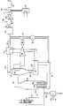
- The above description, as well as further objects, features and advantages of the present invention will be more fully appreciated by reference to the following detailed description of the presently preferred but nonetheless illustrative embodiments in accordance with the present invention when taken in conjunction with the accompanying drawing which is a schematic representation of the system of the present invention.
- Referring to the drawing, the
reference numeral 10 refers, in general, to an entrained flow gasifier which receives oxygen, coal and steam fromconduits gasifier 10 is connected, via aduct 16, to anentrainment vessel 20 having an inlet opening in the lower portion of one wall thereof which communicates with the duct. The coal is gasified in the presence of the oxygen and steam in thegasifier 10 in a conventional manner to produce a syngas which is mixed with solid ash particles in the vessel. Thus, a mixture of the syngas and the entrained particles from thegasifier 10 are introduced into thevessel 20 for reasons to be described. - An outlet is formed at the upper portion of the
vessel 20 which communicates, via aconduit 22, to acyclone separator 24 which receives the mixture of gases and particles and operates to separate the gases from the particles in a conventional manner. A bundle ofexchange tubes 25 is provided in theseparator 24 and is connected in a flow circuit including asteam turbine 26 for circulating water or steam through the bundle to transfer heat from the gases and particles in the separator to the water or steam for passage to the turbine. Theturbine 26 is drivingly connected to an electrical generator 28 to generate electrical power. Since thecyclone separator 24, thetube bundle 25, theturbine 26, and the generator 28 are conventional, they will not be described in any further detail. - A gas outlet is provided in the upper portion of the
separator 24 and is connected, via aduct 29, to aheat exchanger 30 which operates in a conventional manner to transfer heat from the gases received from the duct to water or steam flow circuitry forming a part of the steam generation cycle discussed above and thus connected to thesteam turbine 26. The outlet of theheat exchanger 30 is connected, via aduct 32, to a conventional scrubber 34 to remove sulfur and other impurities from the gases. Aduct 36 connects the scrubber to acombustor 38 which, in turn, is connected, via aduct 40, to agas turbine 42 which drives acompressor 44 which is in driving engagement with anelectrical generator 46. In thecombustor 38 the gases are mixed with air from thecompressor 44 for combustion and then expanded thru thegas turbine 42 to drive theelectrical generator 46 to generate electrical power. Aheat exchanger 48 is connected to the outlet of thecompressor 44 and utilizes heat from the gas turbine exhaust to heat steam which is circulated through the above-mentioned flow circuit including thesteam turbine 26. - The
separator 24 includes an outlet for the separated particles which is connected, via aduct 49, to a fluidizedbed heat exchanger 50 which also operates in a conventional manner to transfer heat from the separated particles to water or steam flow circuitry contained therein and forming a part of the aforementioned steam generation cycle including thesteam turbine 26. It is understood that thetube bundle 25 and the flow circuitry in theheat exchangers - A
duct 52 connects the cooled particle outlet of theheat exchanger 50 to the lower end of theentrainment vessel 20. Theduct 52 branches into three or more slightly-spacedvertical distributors vessel 20 and into the interior of the vessel for introducing the relatively cool solids into the interior of thevessel 20 for reasons to be described. - A
duct 56 connects theduct 32 to theduct 52 and ablower 58 is provided in theduct 56 for utilizing a portion of the gases from theduct 32 to transport the relatively cool particles from theheat exchanger 50 into thevessel 20 and to fluidize the solids in theheat exchanger 50. - A
duct 60 extends from theduct 16 for receiving any relatively large particles and passing then to a quencher which receives water from apipe 64 and cools the particles before they are passed to a lock hopper, or the like. - In operation, a carbonaceous fuel, such as crushed coal, is introduced into the
gasifier 10 through the conduit 13 along with a sufficient quantity of oxygen and steam through theconduits duct 16, into theentrainment vessel 20 where it is cooled in a marker to be described, before it is passed, via theduct 22, to theseparator 24. - The cooled mixture of syngas and solid particles is further cooled in the
separator 24 by the heat exchange with relatively cool water or steam passing through thetube bundle 25 before the heated water or steam is passed to thesteam turbine 26 for driving the generator 28. Theseparator 24 operates to separate the syngas from the particles, and the former is passed, via theduct 29, to theheat exchanger 30, and the latter is passed, via theduct 49, to theheat exchanger 50. Heat is transferred from the syngas in theheat exchanger 30 to water or steam passing through the flow circuitry associated with theheat exchanger 30 to still further cool the syngas before the heated water or steam is passed to thesteam turbine 26. The cooled syngas from theheat exchanger 30 is then passed, via theduct 32, to the scrubber 34 and, then tocombustor 38 where the gas is combusted and expanded through thegas turbine 42 to drive theelectrical generator 46. The exhaust of thegas turbine 42 is passed to theheat exchanger 48 for heating steam which is circulated through the flow circuit including thesteam turbine 26. - The separated particles in the
heat exchanger 50 are fluidized and their heat is transferred to water or steam passing through the flow circuitry connecting theheat exchanger 50 with thesteam turbine 26 to still further cool the particles to a temperature of approximately 1000°F. The cooled particles are then passed, via theduct 52 and thebranch ducts entrainment vessel 20 where they mix with, and absorb heat from, the mixture of syngas and relatively hot particles passing therethrough as described above. This heat exchange is sufficient to lower the temperature of the particles in the syngas-solids mixture, to a temperature of approximately 1600°F which is lower than the softening temperature of the particles. In the above process of mixing, some agglomeration of ash will occur and the agglomerated ash will be withdrawn thruduct 60, quenched in thecooler 62 and passed to external equipment for disposal. The remaining finer ash at 1600°F is thus rendered non-sticking and will not deposit on any downstream heat transfer surfaces. - A portion of the syngas is tapped from the
duct 32 and passed, via theduct 56, to theduct 52 to pneumatically assist the movement of the particles from theheat exchanger 50 to thevessel 20 and to fluidize the particles in theheat exchanger 50. Since this syngas is at a relatively low temperature by virtue of having passed through theheat exchanger 30, it does not increase the temperature of the particles. - Therefore, the system and method of the present invention utilizes a combined gas turbine and steam turbine cycle while providing an efficient and clean technique for reducing the temperature of the ash particles to a value below their softening temperature before they are passed through the system.
- It is understood that variations may be made in the foregoing without departing from the scope of the invention. For example, an air preheat system can be used in place of the steam cycle in the
heat exchangers 30 and/or 50 to receive the heat from the gas and the particles, respectively.
Claims (10)
- A method of generating and utilizing heat for the production of power, comprising the steps of gasifying coal in the presence of oxygen and steam to produce a mixture of gas and solid particles of ash, cooling said mixture, then separating said gas from said particles, and removing heat from said separated particles to further cool said particles, said step of cooling comprising the step of passing said further cooled particles in a heat exchange relation with said mixture.
- The method of Claim 1 further comprising the steps of transferring heat from said gas to water or steam to further cool said gas, and passing said steam to a steam turbine for driving same.
- The method of Claim 1 or 2 further comprising the step of passing said separated gas to a gas turbine to drive same.
- The method of Claim 3 wherein said separated gas is passed to said gas turbine after said step of transferring heat.
- The method of any preceding claim wherein said step of removing heat from said separated particles comprises the step of passing steam or water in a heat exchange relation with said separated particles to heat said water or steam.
- The method of any preceding claim wherein, in said step of cooling, said particles are cooled below their softening temperature to prevent sticking thereof.
- The method of any preceding claim further comprising the step of further cooling said gas and said particles during said step of separating.
- The method of any preceding claim further comprising the steps of passing a portion of said separated gas to said further cooled particles to pneumatically assist the passage of said further cooled particles to said mixture.
- A method of generating the utilizing heat, comprising the steps of gasifying coal particles in the presence of oxygen and steam to produce a mixture of gas and solid particles including ash, cooling said mixture, separating said gas from said particles while simultaneously further cooling said gas and said particles, passing said separated gas to a heat exchanger for still further cooling said gas, then passing said cooled, separated gas to a gas turbine for driving same, and passing said separated particles to a heat exchanger for still further cooling said particles.
- A system for generating and utilizing heat for the production of power, comprising means for gasifying coal in the presence of oxygen and steam to produce a mixture of gas and solid particles including ash, means for cooling said mixture, means for treating said cooled mixture to separate said gas from said particles, means for removing heat from said separated particles to further cool said particles, and means for passing said further cooled particles to said cooling means, said cooling means comprising means for passing said further cooled particles in a heat exchange relation with said mixture.
Applications Claiming Priority (2)
| Application Number | Priority Date | Filing Date | Title |
|---|---|---|---|
| US08/089,983 US5375408A (en) | 1993-07-06 | 1993-07-06 | Combined-cycle power generation system using a coal-fired gasifier |
| US89983 | 1993-07-06 |
Publications (1)
| Publication Number | Publication Date |
|---|---|
| EP0633303A1 true EP0633303A1 (en) | 1995-01-11 |
Family
ID=22220531
Family Applications (1)
| Application Number | Title | Priority Date | Filing Date |
|---|---|---|---|
| EP94304246A Withdrawn EP0633303A1 (en) | 1993-07-06 | 1994-06-13 | Combined-cycle power generation system using a coal-fired gasifier |
Country Status (6)
| Country | Link |
|---|---|
| US (1) | US5375408A (en) |
| EP (1) | EP0633303A1 (en) |
| JP (1) | JP2673783B2 (en) |
| KR (1) | KR950003424A (en) |
| CN (1) | CN1102872A (en) |
| CA (1) | CA2123465A1 (en) |
Cited By (2)
| Publication number | Priority date | Publication date | Assignee | Title |
|---|---|---|---|---|
| EP0668343A1 (en) * | 1994-02-18 | 1995-08-23 | Foster Wheeler Energy Corporation | A method and apparatus for cleaning and cooling synthesized gas |
| EP0725127A1 (en) * | 1995-02-03 | 1996-08-07 | Metallgesellschaft Ag | Process for gasification of a material containing combustible substances in a circulating fluidized bed |
Families Citing this family (14)
| Publication number | Priority date | Publication date | Assignee | Title |
|---|---|---|---|---|
| US5469698A (en) * | 1994-08-25 | 1995-11-28 | Foster Wheeler Usa Corporation | Pressurized circulating fluidized bed reactor combined cycle power generation system |
| AU714670B2 (en) * | 1995-08-01 | 2000-01-06 | Dut Pty Ltd | Improvements in the use of carbonaceous fuels |
| AUPN451795A0 (en) * | 1995-08-01 | 1995-08-24 | Isentropic Systems Ltd | Improvements in the use of carbonaceous fuels |
| WO2008096379A1 (en) * | 2007-02-07 | 2008-08-14 | A.G.T. S.R.L. | Gasification plant |
| GB0808200D0 (en) * | 2008-05-06 | 2008-06-11 | Invista Technologies Srl | Power recovery |
| CN102373099B (en) * | 2010-08-20 | 2013-12-11 | 新奥科技发展有限公司 | Method for coupling coal gasification process and steam turbine power generation process |
| CN102373091B (en) * | 2010-08-20 | 2013-12-11 | 新奥科技发展有限公司 | Method for coupling coal gasification process and steam turbine power generation process |
| CN102373096B (en) * | 2010-08-20 | 2013-12-11 | 新奥科技发展有限公司 | Coupling method of coal gasification technology and steam turbine generating technology |
| CN102373090B (en) * | 2010-08-20 | 2013-10-16 | 新奥科技发展有限公司 | Coal gasification technology and steam turbine power generation technology coupled method |
| CN102373092B (en) * | 2010-08-20 | 2013-10-16 | 新奥科技发展有限公司 | Coupling method of coal gasification technology and steam turbine generating technology |
| CN102373098B (en) * | 2010-08-20 | 2013-10-16 | 新奥科技发展有限公司 | Coupling method of coal gasification technology and steam turbine generating technology |
| CN102373097B (en) * | 2010-08-20 | 2013-12-11 | 新奥科技发展有限公司 | Coupling method of coal gasification process, residual carbon oxidation process and steam turbine power generation process |
| CN102559269B (en) * | 2010-08-20 | 2015-03-04 | 新奥科技发展有限公司 | Method for combining coal gasification process and vapor turbine power generation process |
| CN102518489B (en) * | 2012-01-06 | 2016-08-03 | 新奥科技发展有限公司 | Electricity-generating method, the device generated electricity for gasified production of energy products and heat |
Citations (5)
| Publication number | Priority date | Publication date | Assignee | Title |
|---|---|---|---|---|
| US3991557A (en) * | 1974-07-22 | 1976-11-16 | Donath Ernest E | Process for converting high sulfur coal to low sulfur power plant fuel |
| US4198212A (en) * | 1977-05-24 | 1980-04-15 | The Lummus Company | Coal gasification effluent treatment |
| EP0082673A2 (en) * | 1981-12-17 | 1983-06-29 | YORK-SHIPLEY, Inc. | Fast fluidized bed reactor and method of operating the reactor |
| GB2115129A (en) * | 1982-02-15 | 1983-09-01 | Shell Int Research | Process for the cooling of small particles-containing gases |
| US4482358A (en) * | 1983-03-17 | 1984-11-13 | General Electric Company | Granular bed filtering device |
Family Cites Families (13)
| Publication number | Priority date | Publication date | Assignee | Title |
|---|---|---|---|---|
| US3002347A (en) * | 1956-05-24 | 1961-10-03 | Babcock & Wilcox Co | Method and apparatus for a binary fluid power plant |
| US3868817A (en) * | 1973-12-27 | 1975-03-04 | Texaco Inc | Gas turbine process utilizing purified fuel gas |
| US3968348A (en) * | 1974-05-31 | 1976-07-06 | Stanfield Phillip W | Container heating jacket |
| US4184322A (en) * | 1976-06-21 | 1980-01-22 | Texaco Inc. | Partial oxidation process |
| CH623888A5 (en) * | 1977-10-04 | 1981-06-30 | Bbc Brown Boveri & Cie | |
| US4212160A (en) * | 1977-12-22 | 1980-07-15 | Combustion Engineering, Inc. | Combined cycle power plant using low Btu gas |
| DE2835852C2 (en) * | 1978-08-16 | 1982-11-25 | Kraftwerk Union AG, 4330 Mülheim | Combined gas-steam power plant with a gasification device for the fuel |
| DE3113993A1 (en) * | 1981-04-07 | 1982-11-11 | Metallgesellschaft Ag, 6000 Frankfurt | METHOD FOR THE SIMULTANEOUS PRODUCTION OF COMBUSTION GAS AND PROCESS HEAT FROM CARBON-MATERIAL MATERIALS |
| JPS614790A (en) * | 1984-06-09 | 1986-01-10 | エル・ウント・ツエ・シユタインミユラア・ゲゼルシヤフト・ミツト・ベシユレンクテル・ハフツング | Method and device for separating and exhausting solids from treating gas under pressure |
| DE3446715A1 (en) * | 1984-12-21 | 1986-06-26 | Krupp Koppers GmbH, 4300 Essen | METHOD FOR COOLING PARTIAL OXIDATION GAS CONTAINING DUST-BASED IMPURITIES, INTENDED FOR USE IN A COMBINED GAS STEAM TURBINE POWER PLANT |
| DE3612888A1 (en) * | 1986-04-17 | 1987-10-29 | Metallgesellschaft Ag | COMBINED GAS / STEAM TURBINE PROCESS |
| IE63440B1 (en) * | 1989-02-23 | 1995-04-19 | Enserch Int Investment | Improvements in operating flexibility in integrated gasification combined cycle power stations |
| JPH046238A (en) * | 1990-04-25 | 1992-01-10 | Mitsubishi Alum Co Ltd | High toughness al alloy foil excellent in corrosion resistance |
-
1993
- 1993-07-06 US US08/089,983 patent/US5375408A/en not_active Expired - Lifetime
-
1994
- 1994-05-12 CA CA002123465A patent/CA2123465A1/en not_active Abandoned
- 1994-06-13 EP EP94304246A patent/EP0633303A1/en not_active Withdrawn
- 1994-06-15 KR KR1019940013420A patent/KR950003424A/en not_active Application Discontinuation
- 1994-06-17 JP JP6135263A patent/JP2673783B2/en not_active Expired - Lifetime
- 1994-06-24 CN CN94107817A patent/CN1102872A/en active Pending
Patent Citations (5)
| Publication number | Priority date | Publication date | Assignee | Title |
|---|---|---|---|---|
| US3991557A (en) * | 1974-07-22 | 1976-11-16 | Donath Ernest E | Process for converting high sulfur coal to low sulfur power plant fuel |
| US4198212A (en) * | 1977-05-24 | 1980-04-15 | The Lummus Company | Coal gasification effluent treatment |
| EP0082673A2 (en) * | 1981-12-17 | 1983-06-29 | YORK-SHIPLEY, Inc. | Fast fluidized bed reactor and method of operating the reactor |
| GB2115129A (en) * | 1982-02-15 | 1983-09-01 | Shell Int Research | Process for the cooling of small particles-containing gases |
| US4482358A (en) * | 1983-03-17 | 1984-11-13 | General Electric Company | Granular bed filtering device |
Cited By (2)
| Publication number | Priority date | Publication date | Assignee | Title |
|---|---|---|---|---|
| EP0668343A1 (en) * | 1994-02-18 | 1995-08-23 | Foster Wheeler Energy Corporation | A method and apparatus for cleaning and cooling synthesized gas |
| EP0725127A1 (en) * | 1995-02-03 | 1996-08-07 | Metallgesellschaft Ag | Process for gasification of a material containing combustible substances in a circulating fluidized bed |
Also Published As
| Publication number | Publication date |
|---|---|
| JPH0734899A (en) | 1995-02-03 |
| JP2673783B2 (en) | 1997-11-05 |
| CN1102872A (en) | 1995-05-24 |
| CA2123465A1 (en) | 1995-01-07 |
| KR950003424A (en) | 1995-02-16 |
| US5375408A (en) | 1994-12-27 |
Similar Documents
| Publication | Publication Date | Title |
|---|---|---|
| US5375408A (en) | Combined-cycle power generation system using a coal-fired gasifier | |
| US3804606A (en) | Apparatus and method for desulfurizing and completely gasifying coal | |
| JP2954972B2 (en) | Gasification gas combustion gas turbine power plant | |
| US5666801A (en) | Combined cycle power plant with integrated CFB devolatilizer and CFB boiler | |
| US20040237404A1 (en) | Hot solids gasifier with CO2 removal and hydrogen production | |
| JPH0713234B2 (en) | Power generation method and apparatus utilizing gasification of carbon-containing fuel | |
| SE436760B (en) | PROCEDURE FOR DIRECT REDUCTION OF IRON OXIDE WITH THE REDUCING GAS | |
| JPH02500447A (en) | Coal gasification method and fluidized bed gas generator for carrying out the method | |
| US11193073B2 (en) | All-steam gasification for supercritical CO2 cycle system | |
| US4590868A (en) | Coal-fired combined plant | |
| WO2007094908A2 (en) | Integrated gasification combined cycle with preheating of nitrogen / oxygen from air separator | |
| US20230151286A1 (en) | Char Preparation System and Gasifier for All-Steam Gasification with Carbon Capture | |
| JPS63223334A (en) | Coal burning type boiler | |
| KR20000015802A (en) | Coal gasification apparatus, coal gasification method and integrated coal gasification combined cycle power generating system | |
| US4346302A (en) | Oxygen blown coal gasifier supplying MHD-steam power plant | |
| JPS6150995B2 (en) | ||
| US5517818A (en) | Gas generation apparatus | |
| JPH10279960A (en) | Fluidized bed gasification | |
| JP2000328074A (en) | Coal gasification system | |
| US5987874A (en) | Method and apparatus for power generation based on char and a fluidized bed reactor | |
| HU217014B (en) | Method and apparatus for producing gases for operating gas-turbines of combined gas and steam operated power station | |
| CN1041531C (en) | Method of and apparatus for producing combustible gases from pulverized solid fuel | |
| EP1105446A1 (en) | Method of producing a clean gas from a hydrocarbon | |
| JPS6069410A (en) | Coal burning combined plant | |
| JPH09328690A (en) | Multi-functional heat recovery type coal gasification system |
Legal Events
| Date | Code | Title | Description |
|---|---|---|---|
| PUAI | Public reference made under article 153(3) epc to a published international application that has entered the european phase |
Free format text: ORIGINAL CODE: 0009012 |
|
| AK | Designated contracting states |
Kind code of ref document: A1 Designated state(s): ES GB IT PT |
|
| 17P | Request for examination filed |
Effective date: 19950606 |
|
| STAA | Information on the status of an ep patent application or granted ep patent |
Free format text: STATUS: THE APPLICATION HAS BEEN WITHDRAWN |
|
| 18W | Application withdrawn |
Withdrawal date: 19960705 |